Exploration on the safety significance of goaf treatment and derivative disaster prevention and control in large-structure subsequent filling stope
abstract
The safety of goaf treatment and disaster prevention and control in large-structure subsequent filling stope is of great significance. Taking Anhui Development Mining Co., Ltd. as an example, the prevention and control measures for direct disasters in goaf are discussed from two aspects: goaf detection and goaf management, and the prevention and control measures for goaf derived disasters are discussed from the perspective of mining process control. The analysis results have certain reference significance for disaster prevention and control in goaf areas in similar mines.

Author and unit
Yu Zhenjian
Anhui Development Mining Co., Ltd
citation styles
:
text
Goaf areas formed by underground mining can cause various forms of disasters such as roof falling, water permeability, earthquakes, rock burst, rock burst, ground collapse, ground fissures, and the resulting surface landslides, mudslides, and vegetation damage, which may cause Major casualties and property damage accidents. According to statistics, the subsidence area caused by mining in China reaches 1,150 km2. There are more than 30 mining cities where mining subsidence disasters occur, causing losses of more than 400 million yuan each year. Among them, deaths caused by goaf accidents account for 53% of the total deaths in metal and non-metallic mining accidents. Therefore, goaf prevention and control is an important task that non-coal mines must pay attention to. This paper takes the goaf formed by the sublevel drilling stage open-stope and subsequent filling mining method at the Liliou-Wuji Iron Mine of Anhui Development Mining Co., Ltd. as the research object, studies and discusses goaf filling methods, optimizes mining technology, and prevents goaf disasters and derivative disasters.
1 Project overview
Anhui Development Mining Co., Ltd. was established in July 2003. It is a large-scale iron ore mining and dressing joint enterprise. It owns two ore bodies, Lilou and Wuji (northern section), with geological reserves of 381 million tons. The deposit is of sedimentary metamorphic type, generally occurring in steeply inclined stratified and quasi-stratified. The average thickness of the ore body is 48 m, and some sporadic ore bodies are 2 - 6 m thick. The ore beds are mainly produced in metamorphic quartz schist and iron-blende quartz schist, and have good stability. The roof and floor of the ore body are layered or sheet-like rocks, with developed bedding and foliation. Affected by metamorphism, the layer bonding force is strong. In the weathered zone, most of them are weathered, separated and dissolved along the bedding. Therefore, the rock mass of the roof and floor in some shallowly buried areas is poor. The rock mass strength is low, and the roof of some goaf areas collapses due to untimely filling. Anhui Development Mining Co., Ltd. adopts the segmented drilling stage open stope followed by filling mining method. The stope width is 20 m, the segmented height is 25 m, and the stage height is 100 m. Currently, mining in the middle section of-400 m is being carried out. The filling method and the sealing method are mainly used to treat the goaf.
2 Goaf treatment process
In order to effectively avoid safety hazards and ore losses caused by stope roof collapse, the geometry of the goaf is generally first scanned and detected by three-dimensional scanning, and combined with the data of the ground pressure monitoring system of the entire mine to determine whether to adopt sealing or filling. Treatment plan. If it is determined to use filling method to treat the goaf, further design of corresponding filling plans is needed.
2.1 goaf detection
Goaf detection is the primary condition for goaf stability analysis, comprehensive management and prevention of goaf accidents. Understanding the geometry of the goaf before filling is the basis for reasonable design of filling plans. Currently, the company uses IMGER5010 and C-ALS three-dimensional laser scanners for goaf detection. The IMGER5010 detects from the bottom of the goaf upwards, and the C-ALS detects from the upper part of the goaf through a probe hole. The three-dimensional laser scanner has high detection accuracy, and the detected three-dimensional geometric space data of the goaf can provide a reliable basis for the next step of goaf processing.
2.2 ground pressure monitoring
The entire mine has established a ground pressure monitoring system to monitor the displacement of roadway roof, floor, etc. The ground pressure monitoring system is used to monitor stress in the working area, and a regular data analysis system has been established. If it is found through the ground pressure monitoring system that the ground pressure in some areas has increased sharply in a short period of time, an emergency plan needs to be activated immediately, the operators should be evacuated in time, and the goaf filling in this area should be prioritized. In addition, observation points covering the entire mine are established in the surface area of the ore body, and total stations are used to conduct observations every quarter to ensure surface safety. Through the above monitoring data, we can understand the ground pressure behavior laws of stope in different areas and provide basis for the treatment of goaf areas in different areas.
2.3 Goaf treatment measures
The goaf after mining thick and large ore bodies is generally treated by filling method, while the goaf after mining scattered small ore bodies is treated by sealing method.
2.3.1 blocking
The sealing method is suitable for treating goaf formed after mining isolated small ore bodies, goaf formed after mining end ore bodies, goaf formed after mining end ore bodies, and goaf above large ore bodies that need to continue mining in accordance with the methods of sealing, isolation and dredging. According to the project progress, the lower ore body of Lilou Iron Mine (-200 to-500 m level) is to be mined. Therefore, the goaf that has been mined at-200 m level but has not yet been filled is treated with a sealing method, and the entire roadway at-200 m level and above is closed to prevent disasters caused by the collapse of the goaf.
2.3.2充填法
Filling method is the most effective measure to prevent goaf disasters. The filling method uses waste rock or wet filling material transported from the pit to fill the goaf, thereby limiting the movement of surrounding rock. At present, the filling methods commonly used in Anhui's development mining industry include tailings cemented filling, waste rock cemented filling and grouting filling.
2.3.2.1 Tailings cemented filling
When ore block mining is completed, preparations for filling are carried out immediately. The filling pipeline is laid into the-275 or-300 m horizontal filling well or filling hole in the upper part of the stope. The filling preparation work first seals the stope to separate the entire stope from all surrounding shafts and lanes. The company mainly uses steel structure retaining walls or concrete retaining walls to block the goaf. The structural retaining wall at the bottom of the stope is arranged on the ore exit road, and the retaining wall at the upper part of the stope is arranged at the entrance of the drilling lane. The second is to seal and isolate tunnels, boreholes and other channels around the goaf to prevent filling and slurry leakage; filter pipes are arranged in the stope to reduce water accumulation in the goaf. After the partition walls and water filtering facilities pass the inspection, filling can begin. Filling slurry is directly filled into the goaf through filling pipelines. Stope filling adopts phased and divided filling methods, and continues to fill after the previous filling material has initially solidified until the stope is full.
The stope filling is stopped when it is 3 meters away from the roof. After the lower filling body shrinks and stabilizes for one month, the upper space will be forcibly connected to the roof in stages. Process control needs to be strengthened during the filling process to ensure that the strength and quality of the filling body meet the requirements.
2.3.2.2 Waste stone cemented filling
Waste rock cemented filling is generally aimed at two-step mining goaf with stable surrounding rock conditions. First, a three-dimensional laser scanner is used to scan the empty area, and the waste rock cementation filling design is carried out based on the scanning results. Generally, the rock discharge chute is constructed 25 meters above the goaf, and then the inclined chute is constructed to add car blocks to ensure that operators and equipment maintain a certain distance from the goaf boundary to ensure the safety of waste rock discharge. After filling the bottom of the stope with waste rock at a height of 10 meters, waste rock cementation and filling are carried out while draining waste rock and filling. Finally, core testing was carried out on the waste stone cemented filling body to determine that the strength of the waste stone cemented filling body met the design requirements. The advantage of adopting this filling method is that it can effectively reduce the cost of rock drainage and filling.
2.3.2.3 Grouting and filling
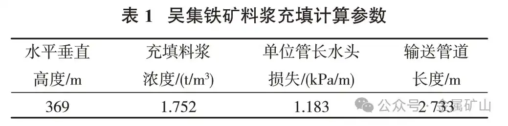
In view of the special situation that a certain two-step mining pillar collapsed during mining in two adjacent one-step stope, resulting in penetration of the goaf due to the collapse, filling measures (filling lanes and filling holes) were first constructed in the upper and middle section. To the top of the stope, the surface filling station was used to carry out grouting filling treatment on the goaf of the collapsed stope. Based on theoretical calculations of slurry static pressure, conveying height, head loss and other data (Table 1), a reasonable conveying plan is designed to achieve high-power offline self-flow filling of the filling slurry. Using grouting filling method can effectively reduce the exposed area of the side walls of the goaf and achieve stability of the goaf.
 3 Disaster prevention and control measures in goaf areas
Although the Lilou-Wuji Iron Mine adopts the fill mining method and fills most of the goaf, due to the needs of production organization, there are still a certain number of reasonably turnover goaf underground, that is, it is difficult for the newly formed goaf to realize the filling operation will start immediately after the completion of ore mining, and the goaf will remain open for a certain period of time. During the two-step mining process, excessive blasting vibration and insufficient insulation wall thickness will induce the collapse of the side walls of the goaf and cause geological disasters; if ore extraction at the bottom of the goaf is unreasonable or not blocked in time, it will easily cause ore to rush into the ore extraction tunnel or cause air shock waves, etc., threatening the safety of personnel and equipment. Therefore, it is very necessary to prevent and control goaf disasters and derivative disasters.
3.1 Control blasting sequence
The middle advanced cutting and two sides lateral extrusion and collapse technology realizes that ore supports the pillars on both sides of the stope after blasting, reduces the exposed area of the side walls of the goaf, effectively maintains the stability of the goaf, and reduces the impact of blasting on the filling body.
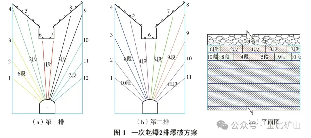
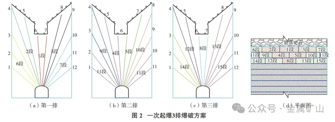
Figure 1 and Figure 2 show two forms of lateral extrusion ore caving technology for middle advanced cutting and two sides. One is that when two rows of gunholes are broken down at one time, the six holes in the middle of the first row are first detonated with 1, 2, and 3 segments of detonators respectively, and then the four holes in the middle of the second row are detonated with 4 and 5 segments; Finally, the holes on both sides of the first row are subjected to 6 and 7 segments of detonators, and the holes on both sides of the second row are subjected to 8, 9, and 10 segments of blasting in turn. The other is that when three rows of gunholes are blasted at one time, the six holes in the middle of the first row are first detonated with 1, 2, and 3 segments of detonators respectively, and then the four holes in the middle of the second row are detonated with 4 and 5 segments, and then the two holes in the middle of the third row are detonated with 8 segments of detonators; Finally, 6 and 7 sections of detonators were used for the holes on both sides of the first row, 9, 10, and 11 sections of the holes on both sides of the second row, and 12, 13, 14, and 15 sections of the third row were used for lateral extrusion blasting. The latter detonates in advance in the middle hole in the platoon, forming a "V"-shaped free surface in advance. When blasting the holes on both sides, three free surfaces are formed, which reduces blasting pinching and reduces blasting damage to adjacent stope or filling bodies. damage.
This blasting method was implemented in Lilou No. 18-6 stope, and the blasting effect was good. According to the scanning results of the three-dimensional scanner, it had little impact on the filling bodies on both sides of the goaf, effectively improving the stability of the filling bodies on both sides of the goaf.
3.2 Control goaf exposure
After the upper horizontal blasting is completed, each ore drawing approach at the bottom of the stope will balance the ore, thereby maintaining an even decline in the stope ore. However, during the ore drawing process, there are cases of open areas in the ore drawing approach and uneven ore drawing. At this time, the open holes in the ore drawing approach must be effectively blocked in time to prevent personnel injury caused by the collapse of filling bodies or ore bodies on both sides. or equipment damage. Finally, the residual ore is recovered by using a remote-controlled oil shovel. The operators of the remote-controlled oil shovel should be as far away as possible from the exposed part of the goaf and work closely to the tunnel wall to prevent the shock wave formed by the collapse of the goaf from causing harm to personnel.
3.3 Control wall thickness
During the underground stope mining process, the boundary of the ore body in the two-step mining process needs to be determined in combination with the three-dimensional laser scanning boundaries of the goaf on both sides. However, as the two-step mining site begins to be large-scale, the filling body collapses, which not only affects the ore production quality and the safety of the goaf. Therefore, it is very important to reasonably determine the thickness of the retaining wall.
The thickness of the retaining wall should be the minimum resistance line of sector-shaped medium and deep holes. According to the ore properties, the Lilou-Wuji ore body is hard ore. Based on experience, it is necessary to expand the thickness of the retaining wall from the original 1 m to 1.8~2.4 m. Specific adjustments to the retaining wall should be continuously revised based on the stability of the ore body itself and actual production experience. Increasing the thickness of the retaining wall can effectively reduce the damage to the filling body by blasting and enhance the stability of the goaf.
4 Conclusion
(1) Aiming at the treatment of goaf and its disaster prevention and control issues, Liliou-Wuji Iron Mine adopts three-dimensional detection of goaf and combines ground pressure monitoring methods to determine different goaf treatment methods, designs different filling plans for filling treatment methods, and proposes different derivative disaster prevention and control plans such as controlling the blasting sequence of medium and deep holes, controlling the exposure of goaf, and controlling the thickness of retaining walls. The company has an annual production capacity of 7.5 million tons, and produces more than 2 million m2 of empty areas every year. has good practical processing effect.
(2) The prevention and control of goaf disasters and derivative disasters is a common problem faced by all underground mines. Anhui Development Mining Co., Ltd. has achieved good goaf management results through filling and sealing methods; goaf disaster prevention and control is a very complex issue that requires each mine to combine reality and continuously summarize and improve its ability to respond to goaf disasters.
(3) The quality of filling and roof connection and the blasting of the next middle section directly affect the safety of the bottom structure of the previous middle section. Therefore, during the excavation process, according to the exposure of surrounding rock, strengthened support methods should be taken to ensure the stability of the bottom structure and prevent safety accidents, such as using shotcrete anchor nets, U-arch supports, masonry, etc.
References (omitted)
